Boreline – Installation

Installation Manual

For a complete installation manual, please send us a request via our contact form. Be sure to specify that you would like the complete installation manual and whether you are an end-user, installer, retailer or other (specify).

Installation Procedure

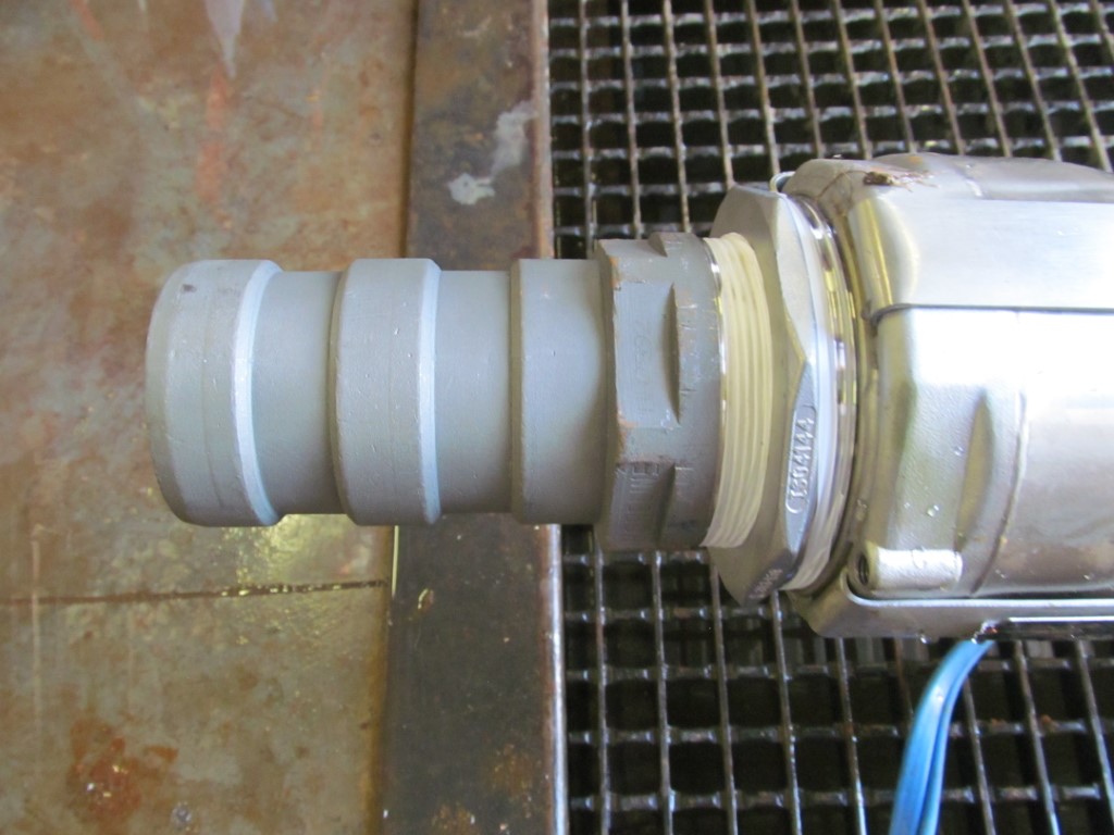
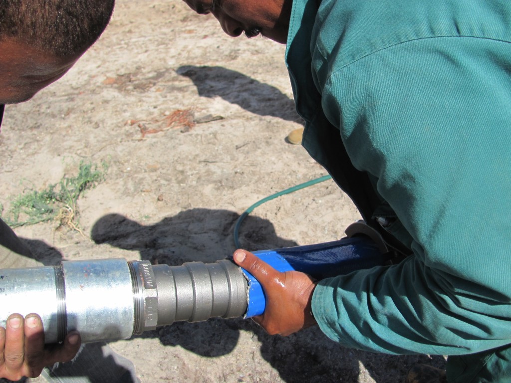
Boreline® has been specifically designed to replace rigid risers. Because of its design, using Boreline® results in major savings in time and labour. A pump and column can be installed and retrieved in a fraction of the time required for the rigid riser. Over the long term, Boreline® does not corrode or scale internally allowing for further savings.

Ensure you have the following on site:

  • Boreline® Couplings. Each coupling consist of a coupling body and two outer rings. The outer rings consist of three equal segments that make up the ring. Each ring has three cap screws.
  • The required length of Boreline®
  • Sufficient Boreline® Cable Straps needed to attach the power cable to the Boreline® along the entire length of the flexible riser (1xCable Strap is needed for each metre of Boreline®).
  • Electrical cable – equal to the length of Boreline® – plus 5%
  • Submersible Pump
  • Base plate and wellhead assembly
  • 2 Boreline® Lifitng Clamps
  • Tripod or crane and the Rolling wheel Assembly
  • Allen keys, knife or hacksaw

If you are not using a break off plug, a 6mm hole can be drilled into the non-return or check valve for easier retrieval of hose. Please note that some pumps manufacturers do not approve of this method and it is best to check with the pump supplier.

The following table serves as a guideline for recommended well casing diameters:

Boreline® Diameter Approx Flat Width Minimum Casing Diameter
Inches mm inches mm inches mm
1 24 1.7 43 3 76
32 2 52 3 76
1 ½ 38 2.6 65 4 102
2 50 3.2 82 4 102
2 ½ 64 4 102 5 127
3 76 4.8 122 6 152
4 102 6.4 162 8 203
5 127 7.9 200 10 255
6 152 9.7 245 12 305
8 203 12.6 320 16** 406**

* Dependant on pump and couplings being used.

For more detailed information, request the latest Installation Manual

  1. Ensure that the ends of the flexible riser are square. Trim with a sharp knife or hacksaw if necessary.
  2. Screw the Boreline® coupling into the out-let of the pump.
  3. Push the Boreline® flexible riser over the coupling body hosetail making sure the Boreline® is flush with the shoulder at the threaded end of the coupling. Note: do not use lubricant.
  4. Fit the first ring, with the three segments, over the recess closest to the threaded end of the coupling body. Tighten all three screws evenly, ensuring the gaps between the segments are even. When fully tightened the gaps between these segments should be approximately 1 – 2mm.
  5. Fit the second ring over the second recess positioning the gaps of the segments half way between the gaps of the segments of the first ring. Tighten the rings as explained above.

Coupling torque settings:

Size Nm
24mm 10
32mm 10
38mm 10
50mm 12
65mm 20
76mm 30
102mm 30
127mm 40
152mm 45
203mm 45
Boreline Coupling fitted to out-let of Pump
click image to enlarge
Fitting the Boreline to the Coupling
click image to enlarge

For more detailed information, request the latest Installation Manual

  1. The Boreline® flexible riser should be laid on the ground with the rib facing up.
  2. Push the Boreline® Cable Strap through each cable rib opening that appears along the entire length of the Boreline®. The openings appear every metre. Turn the Boreline® over as you proceed to the next opening so that by the time all the cable straps have been inserted, the rib of the Boreline® is facing down.
  3. Roll the power cable out next to the Boreline®. Do not walk on the Boreline®.
  4. Connect the power cable to the pump motor. (This work should be carried out by a qualified electrician only)
  5. Starting from the end nearest the pump lift the power cable to the centre of the Boreline®. Bring the cable strap around the power cable, and towards the buckle (use a clovehitch knot). Pull tight, ensuring the power cable is hard against the Boreline® flexible riser. Buckle the strap.
  6. Move to the next cable strap. Before tightening the power cable, snake the power cable along the Boreline®. (see picture). The power cable should be fitted as shown so as to accommodate the extension characteristics of the Boreline® in use.
  7. Repeat the procedure for fastening the cable strap and then move to the next cable strap.
    (Remember to snake the power cable along the entire length of the Boreline® allowing approximately 5% slack, as shown in the picture).
  8. Any additional dipper tubes, high/low level probes etc. can be attached alternatively with the Boreline® Cable strap in the same way as the power cable.

For more detailed information, request the latest Installation Manual

  1. A tripod or crane will be required to lift the pump into the borehole. If a tripod is used it should be positioned directly above the borehole, high enough to allow the pump and Boreline® Lifting Clamp to be raised into the borehole.
  2. Clamp the Boreline® flexible riser only (not the power cable) using the suitable Boreline® Lifting Clamps approximately 500mm above the pump.
  3. Lift the pump by this Lifting Clamp and lower it into the borehole casing until the clamp rests on the wellhead.
  4. Move the rolling wheel over the borehole ensuring that it is centrally positioned and secured. (An unsecured roller can move and cause injury to the operator)
  5. Lift the Boreline® flexible riser over the rolling wheel with the power cable fastened and positioned above the flexible riser.
  6. Attach the second Boreline® Lifting Clamp to the other end of the flexible riser and secure it to the installation vehicle. Reverse the vehicle so that the vehicle now takes the weight of the pump. Remove the first Boreline® Lifting Clamp. (The full load will now be taken by the vehicle and rolling wheel)
  7. Drive the vehicle slowly forward allowing the pump and flexible riser to be lowered into the borehole. Joiners, couplings and Boreline® Lifting Clamp must not pass over the rolling wheel.
  8. When the vehicle is close to the rolling wheel, clamp the flexible riser above the wellhead. Lower the flexible riser slightly so that this clamp now rests on the wellhead. Remove the Boreline® Lifting Clamp from the vehicle.
  9. Attach the second Boreline® coupling and head works to the end of the flexible riser.
  10. Raise the head works using the tripod or crane, remove the Boreline® Lifting Clamp and lower the assembly onto the borehole.

For more detailed information, request the latest Installation Manual

  1. Stop the pump. If a 6mm hole has been drilled into the check valve, allow the water to drain down (10s per foot) to the static water level.
  2. Disconnect the electrical supply and discharge pipe-work.
  3. Lift the Boreline out of the borehole by the headworks (wellhead) for more than 2 metres and clamp the flexible riser with the Boreline Lifting Clamps.
  4. Place the rolling wheel against the borehole. Fold the Boreline over the rolling wheel and attach the headworks (wellhead) to the vehicle. Drive the vehicle away from the borehole so that it takes the weight of the Boreline and pump and remove the Boreline Lifting Clamp.
  5. Drive the vehicle slowly away from the borehole removing the Boreline and pump.
  6. The Red Boreline Straps will indicate when the Pump is close. As the pump approaches the top of the borehole, clamp the flexible riser and allow the clamp to rest on the borehole.
  7. Use the tripod or crane to lift the pump out of the borehole.
  8. Please note: if the Boreline and pump have to be removed while full of water the column will be heavier than normal. In this case make sure to provide for the extra weight when using lifting devices and vehicles.

The table below gives the nominal weight of the Boreline and water column per metre. Please note that the weights of the pump, cable and accessories should be added to establish the total weight of the column.

Boreline® Specifications
Nominal Hose Diameter 1″ 1¼” 1½” 2″ 2½” 3″ 4″ 5″ 6″ 8″
Inside Diameter 25 mm 32 mm 38 mm 50 mm 64 mm 76 mm 102 mm 127 mm 152 mm 202mm
Burst Pressure 85 bar 75 bar 65 bar 65 bar 60 bar 60 bar 58 bar 58 bar 58 bar 45 bar
Recommended Max Operating Pressure 40 bar 30 bar 30 bar 30 bar 25 bar 25 bar 25 bar 22 bar 22 bar 12 bar
Tensile Strength 1,400 kg 1,700 kg 3,000 kg 4,000 kg 6,000 kg 7,000 kg 12,000 kg 16,000 kg 20,000 kg 22,000 kg
Recommended Max Working Load 470 kg 570 kg 1,000 kg 1,300 kg 2,000 kg 2,300 kg 4,000 kg 5,000 kg 6,600 kg 7,300 kg
Weight of Boreline 0.2 kg/m 0.3 kg/m 0.35 kg/m 0.55 kg/m 0.85 kg/m 0.95 kg/m 1.40 kg/m 1.70 kg/m 2.50 kg/m 3.40 kg/m
Minimum Well Diameter 76 mm 102 mm 102 mm 102 mm 152 mm 152 mm 203 mm 255 mm 305 mm 406 mm
Coupling Ring Torque Setting 10 Nm 10 Nm 10 Nm 12 Nm 20 Nm 30 Nm 30 Nm 40 Nm 45 Nm 45 Nm
Max Coupling Diameter 60 mm 65 mm 75 mm 95 mm 110 mm 120 mm 145 mm 175 mm 200 mm 265 mm
SS Coupling Weight 1.0 kg 1.1 kg 1.5 kg 3.5 kg 5.0 kg 6.5 kg 8.5 kg 14 kg 16 kg 43 kg
Weight of Water 0.6 kg/m 1.0 kg/m 1.94 kg/m 2.25 kg/m 3.32 kg/m 5.1 kg/m 9.05 kg/m 14.15 kg/m 20.35 kg/m 31kg/m

Due to continual Research & Development the above specifications are subject to change without notification. 3:1 Safety Factor applied

For more detailed information, request the latest Installation Manual

Print Page